Before video and audio content is sent over a DP link and displayed on the monitor screen a lot of communication has been occurring between a DP source and sink and a possible branch device. Multimedia content transfer in DP Main Data Links is resembling a data link more than e.g. DVI or HDMI. Also, the handshake before the connection is much more comprehensive than just plug-in. Please find below brief definitions of the basic functions of the DP interface and the issues to verify during debugging.
AUX Channel
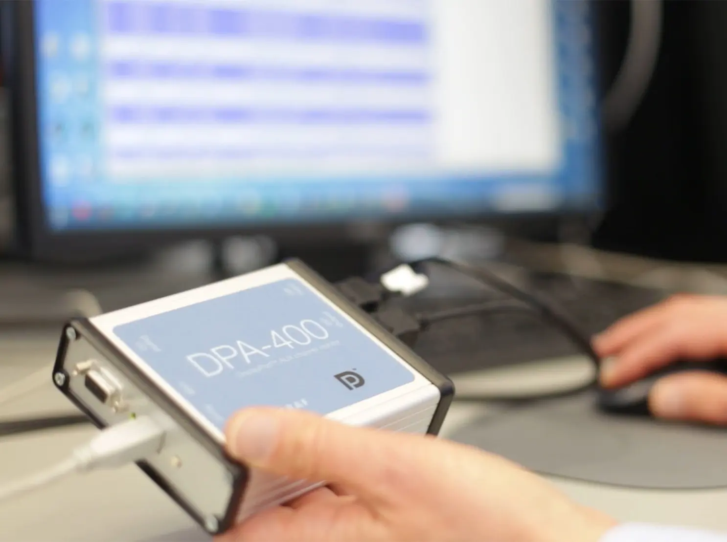
For the handshake between the source and the sink, DP has a dedicated bus, the AUX Channel. Since the source device controls the process, it makes requests for the sink. The only way how the sink can communicate with the source is by issuing a pulse in the Hot Plug Detect (HPD) signal.
Since the AUX Channel is the key element in the source/sink communication, the core to understanding the handshake process is logging the AUX Channel communication. An AUX Channel Monitor tool is must-have equipment for all designers of DP protocol related engineers.
DPCD
The message transfer between DP source and sink occur by reads and writes to the DisplayPort Configuration Data (DPCD) register of the sink device.
By reading certain registers in the DPCD, the source will be aware of the capabilities of the sink. During the process of establishing the data links, the Link Training, source writes to DPCD to indicate the target link configuration and sink in turn whites there the result of each link training stage.
Recalling the detailed meaning of each bit in the tens of DPCD registers is challenging. Therefore it is essential for the productivity of the DP debug process that the tool used readily parses DPCD content in AUX Reads and writes to the terminology commonly used by e.g. VESA DP Specification.
EDID
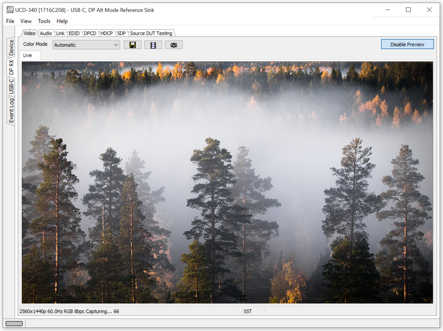
Extended display identification data (EDID) is a bock of structured data defining the capabilities of the DP sink. It defines the make and the model name, the screen size, and the color format. Reading the sink EDID data is one of the first acts that the source is doing once connected to the sink.
Important for the DP source-sink communication is that the EDID defines the native resolution of the sink and the video modes that the sink supports. This data is the basis for the source when it is selecting the format of the content that will be sent to the sink. The resolution, the video mode used, the color format, the audio format, etc.
By altering the EDID of a test sink the engineer can easily verify the flexibility of the sink. An easy to use EDID editor that describes the various bits for the user is another very important and time-saving tool.
Main Link Configuration
Based on the content that the source needs to send to the sink and the sink capabilities read from the EDID and the DPCD the source decides the format of the content sent and the data link configuration used for the transfer. A well-designed source will try to optimize the use of the links and e.g. minimize the power consumption. Therefore its target is to use as few lanes and as low voltage swing as possible.
During the process of the link training, the source initiates the actual training process with its preferred configuration and alters it iteration by iteration until a link is established. Once the link is “up”, the source can start sending the content itself.
By evaluating the communication log of achieved with the help of an AUX Channel Monitor the user verifies how the link training process performs. Again, the easiness of use of the tools will help the engineer to keep focused. Since a link training process between a multi-stream capable source-sink pair can contain hundreds of reads and writes. Features like data highlighting for easy reading and data filtering to concentrate on the essential are vital.
By altering the capability factors of the sink or the source the engineer can verify that his DUT sink or DUT source is performing as expected. Various tests in VESA defined Link Compliance Tests in fact essentially verify that the sink or the source performs in the way needed for good interoperability. A good tool allows for editing and storing the capability data for later use.
MSA and SDP
During the transmission of the content, the source sends also additional data: the Main Stream Attributes (MSA) and the optional Secondary-Data Packets (SDP).
The MSA is the way for the source to inform the sink of the details of the video mode that it is providing. One of the tasks for the engineer is to verify that the MSA and the actual video mode match.
SDP can contain the audio part of the multimedia content and the so-called INFOFRAMES. INFOFRAMES are data defining the structure of the video and the audio – how the sink should interpret it. The engineer will have the same task: verify that the sent data and the content match.
Sideband Messages
When a multi-streaming (MST) capable source connects to a MST capable branch device with sink(s) in its downstream-facing port, the source sends messages to the downstream sinks using Sideband Messaging (Sideband MSG).
In an MST environment, the source device provides the streamed content to all sinks in the set-up. Sideband MSG system is used to get structural and capability information of the sinks available and to send command messages to them.
A tool providing an easily monitored and understood Sideband MSG data will greatly speed up the debug engineer’s job.