USB-C Connector Pins
Connector Pins
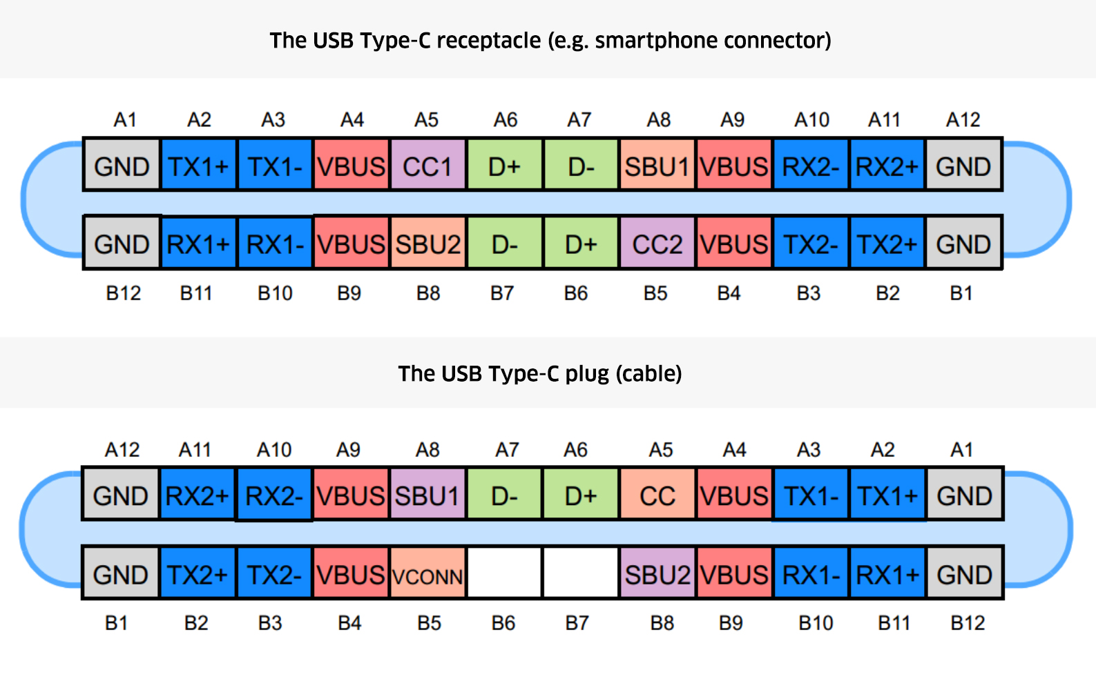
The photo below shows the USB-C connector pins for both receptacle and plug.
Electrical Testing
Unigraf’s unique electrical testing enables testing of the connector pins for soldering or component issues. Thanks to a software-based cable flip, there is no need to replug the cable in order to test both orientations. USB-C electrical test set consists of four tests:
Up Face Port CC and Vconn Test
This test verifies operation of CC lines for short-circuit and open-circuit failures, and that hardware directly related to CC lines is working properly. During the test, TE will operate as Type-C UFP device.
In the start of the test TE temporarily disconnects the CC lines to simulate a re-plug event. After the re-plug event, Ra is connected to CC2, and Rd is connected to CC1. DUT is expected to have Rp, or a current source applied to both CC1 and CC2 lines. The impedance of DUT’s Rp resistor, or current source must be adjusted so that the voltage drop on Rd resistor in TE is within one of the voltage ranges defined by the provided parameters. TE will measure the voltage drop on Rp. Once DUT has started to provide Vconn on CC2, TE will measure the voltage present on CC2. After that TE will do a cable-flip and repeat the steps as above.
AUX (SBU) Lines Test
This test verifies operation of SBU lines for short-circuit and open-circuit failures and that hardware directly related to SBU lines is working properly. During the test the TE will operate as Type-C UFP device. For this test, DUT must support DisplayPort Alternate Mode.
In the start of the test TE temporarily disconnects the CC lines to simulate a re-plug event and waits for DUT to enter DP Alternate mode. Once DUT has entered the DP alternate mode, TE will measure voltage levels on SBU1 (AUX+) and SBU2 (AUX-) lines. Please notice that if TE is acting as DP Sink, it will de-assert HPD signal to keep AUX bus at IDLE state during the voltage measurements. Once the voltages are measured, TE will do a cable-flip and repeat the steps as above.
DUT as Power Sink
This test verifies operation of Vbus and GND lines for short-circuit and open-circuit failures. The test is performed using mandatory PDO for power contract. During the test, the TE will operate as power source, and advertise only vSafe5V for power contract. In order to run this test, the DUT must support Power Sink role.
In the start of the test TE temporarily disconnects the CC lines to simulate a re-plug event and waits for Power Contract to be established. After Power Contact has been established TE will wait for the delay stated in Measurement delay parameter and measures the current in Vbus and GND lines and the voltage of Vbus. The purpose of the delay is to allow the DUT time to stabilize its power consumption.
DUT as Power Source
This test verifies operation Vbus and GND lines for short-circuit and open-circuit failures. During the test, TE will operate as power sink and selects only vSafe5V PDO for power contract. In order to run this test, the DUT must support Power Source role.
In the start of the test TE temporarily disconnects the CC lines to simulate a re-plug event and waits for Power Contract to be established. After Power Contact has been established TE will wait for the delay stated in Power measurement delay parameter and measures the current in Vbus and GND lines and the voltage of Vbus. The purpose of the delay is to allow the DUT time to stabilize its power consumption.
![]()