R&D Debugging
R&D engineers around the world rely on Unigraf’s Test Tools while developing new products in R&D laboratories. Fundamental elements of R&D Debugging are the ease of use, flexibility and state of the art features. With Unigraf’s test tools you can rely on easy-to-use tools with full test automation capabilities.
What to Test?
Video & Audio
New HDMI 2.1 and DisplayPort 2.0 specifications enable video up to 10K resolution. Live preview of the captured video and audio alongside detailed information of the incoming or outgoing streams are a must when determining the stability and quality of the video. Further, different CRC based video tests enable detailed testing of the video stream stability and quality.
Application: Testing transmitter devices
Application: Testing receiver devices
E-learning center: Introducing UCD Console GUI
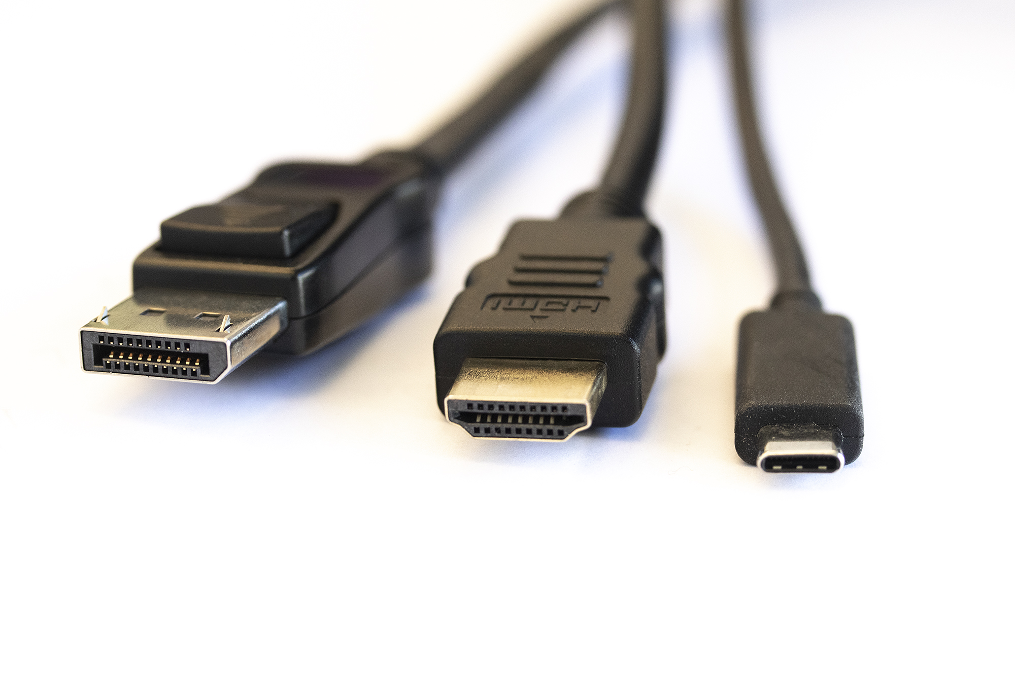
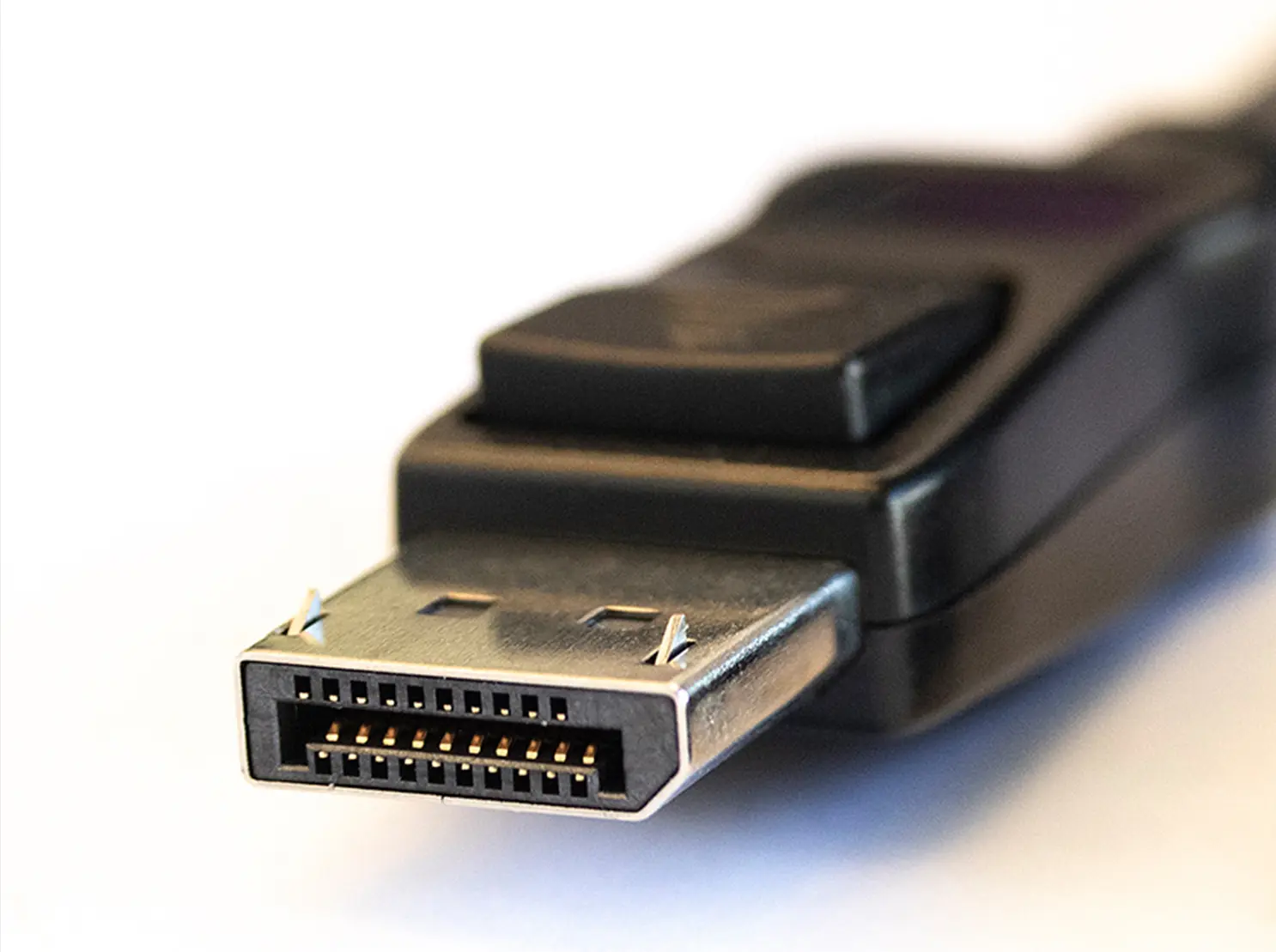
Connector Pins
USB-C Connector Pins
One of the most common manufacturing defects on USB-C devices such as smartphones are poorly soldered connector pins. The USB-C connector is capable of delivering and receiving up to 100W of power. For safety purposes, it is essential to test that the USB-C connector pins are properly soldered into the circuit board. A poorly manufactured USB-C connector can cause the cable or the device to overheat. This has known to cause the melting of the cable or serious overheating of the device causing terminal damage.
HDMI & DisplayPort Connector Pins
Common manufacturing defects on HDMI and DisplayPort devices are poorly manufactured connector pins. A poorly soldered or grounded connector can result as a defected signal which can cause the video to fail. Some modern receiver devices have a high-quality receiver chip which can correct a defected signal. However, all receivers are different and even if your transmitter device works with one monitor, it does not mean that it will work with all monitors. Therefore, it is crucial to use an actual test tool to test HDMI and DisplayPort connectors.
E-learning Center: Testing Connector Pins
AUX Channel
For the handshake between the transmitter and receiver device, DisplayPort has a dedicated bus, the AUX Channel. Since the transmitter device controls the process, it makes requests for the receiver. The only way how the receiver can communicate with the transmitter is by issuing a pulse in the Hot Plug Detect (HPD) signal.
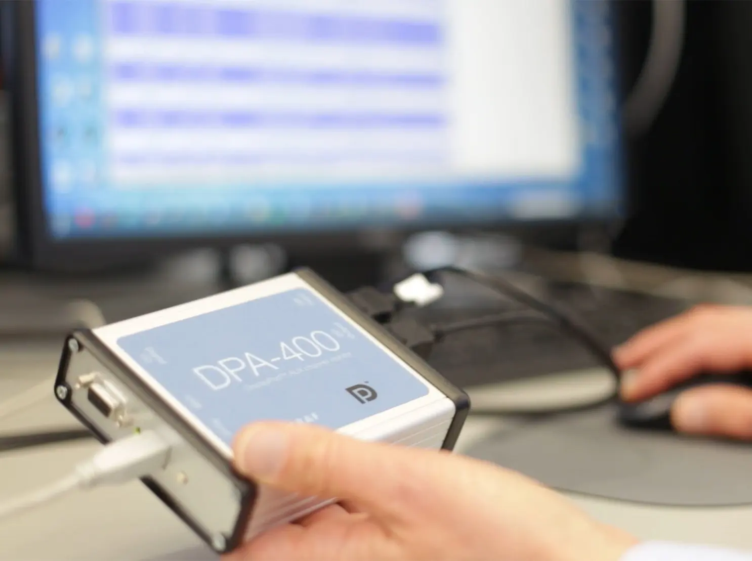
Since the AUX Channel is the key element in the transmitter/receiver communication, the core to understanding the handshake process is logging the AUX Channel communication. AUX Channel Monitor is an essential companion for any DisplayPort test engineer during debugging Link or HDCP protocol related issues or when running Compliance Tests. The capability to analyze the details of the handshake between the Source and the Sink is often the key issue for being able to reveal and solve an interoperability problem. Especially when working with standard Sinks and Sources with limited debugging capabilities, an AUX Channel Monitor will essentially shorten the debugging time.
DPCD
The message transfer between DisplayPort transmitter and receiver occurs by reads and writes to the DisplayPort Configuration Data (DPCD) register of the receiver device. By reading certain registers in the DPCD, the transmitter will be aware of the capabilities of the receiver. During the process of establishing the data links, the Link Training, source writes to DPCD to indicate the target link configuration and the receiver, in turn, writes there the result of each link training stage.
Recalling the detailed meaning of each bit in the tens of DPCD registers is challenging. Therefore it is essential for the productivity of the debug process that the tool used readily parses DPCD content in AUX Reads and writes to the terminology commonly used by e.g. VESA DP Specification.
E-learning center: How to Monitor AUX Channel Communication of DisplayPort
USB-C DisplayPort Alt Mode
Unigraf DPA-400 AUX Channel Monitor is compatible also with DisplayPort Alternate Mode in the USB-C interface. With the Unigraf provided cable, you can connect the DPA-400 between any two USB-C devices and monitor the AUX Channel transactions related to the DP Alt mode.
Link & EDID
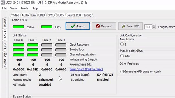
Link
It is crucial to monitor and control the link between the receiver (e.g. monitor) and transmitter device (e.g. game console). With a proper test tool, you can monitor and control the link status.
The video below shows link monitoring feature of UCD Console GUI. You can see the unstable link in lanes 0 and 1 from the error counter and the red color of the link status.
EDID
Extended Display Identification Data (EDID) is a metadata format for display devices (e.g. monitors) to describe their capabilities to a video source (e.g. gaming consoles). When testing transmitter devices, it is crucial to ensure that the device will work with a variety of different kinds of receiver devices (e.g. monitors and TVs).
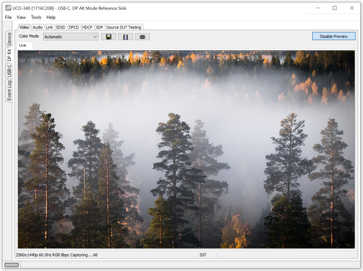
UCD Console comes with a built-in EDID tool. You can use the EDID tool to simulate different monitors and make sure that your transmitter device works seamlessly with different monitors. You can read EDID from receiver devices and save the EDID on your PC. You can then load the EDID file into the UCD series test tools and the test tool will act as the receiver device. Further, a separate EDID Editor enables modifying the EDID.
HDCP Encryption
HDCP content encryption is used in DisplayPort, DVI and HDMI interfaces. For receiver and transmitter devices it’s crucial to be able to read and write HDCP protected content. Further, VESA requires HDCP 2.3 Compliance testing as part of the DisplayPort certification. All Unigraf UCD-series Test Tools offer support for HDCP 1.4/2.3.
Test For Interoperability and Better Quality
Ensure interoperability
Obtaining a certificate from e.g. VESA or DCP requires thorough testing. Only with officially approved test tools you can fully make sure that your transmitter or receiver device works according to the specifications. It is crucial to use the approved test tools already in the development phase as it is the only way to ensure that everything is designed according to the specifications from start to finish. Testing and manufacturing products according to standards are the only way to make sure that your device works seamlessly with other devices available in the market.
Avoid Quality Problems
Proper test tools enable removing human error from testing. For example, some modern monitors and TV’s have high-quality receiver chips that can correct a defected signal. Therefore, even if a transmitter device works with a monitor does not imply that it will work with all monitors. Also, it is impossible for the human eye to detect minor defects in a video stream with a resolution up to 8K@60Hz. Using receiver devices as a test tool for transmitter devices and vice versa is not sufficient.
As the same connector that transfers video, audio and data can transfer power up to 100W, the damage caused by poor design can be extensive. If soldering or assembly of the connector pins is done poorly, there is a chance for the cable or device to overheat and cause some serious damage. Unigarf has developed a unique Electrical Test that you can use to test that all connector pins are properly soldered and assembled. Electrical Test can reveal problems in both power delivery and link caused by poor signal continuity through connector pins.
Automate R&D Debugging
Three Options for Test Automation
With automated testing, you can remove human error from testing and considerably fasten the testing process. In R&D Debugging you can easily select the tests you want to automate and free your time for other tasks while the automated testing sequences take care of the testing. Unigraf’s Test Tools enable three different options for implementing automated testing. Click the link below for detailed information about different test automation options.
Application: Test Automation
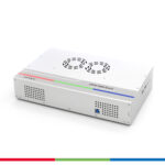
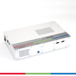
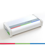
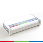
Unigraf UCD Series R&D Debug Tools
Easy-to-Use PC GUI as a Debug Tool
To make the debugging work as easy as possible, all of Unigraf’s test tools share the same PC Graphical User Interface (GUI) called UCD Console. UCD Console adapts to different interfaces (DisplayPort, HDMI, USB-C) and different devices tested (receivers, transmitters and repeaters). PC based GUI enables a convenient size and easy accessibility for the test tools which makes using the test tools easier and more convenient.
E-learning center: Introducing UCD Console
The table below introduces Unigraf’s UCD series test tools and some of their main features.
| UCD-500 | UCD-400 | UCD-422 | UCD-451 | UCD-452 | UCD-340 | UCD-323 | UCD-301 | |
|---|---|---|---|---|---|---|---|---|
| DisplayPort 2.1 Link Layer CTS | ✓ | |||||||
| DP 2.1 UHBR PHY Layer CTS | Gen2 | |||||||
| DisplayPort 1.4a Link Layer CTS | ✓ | ✓ | ||||||
| DP 1.4a HBR3 PHY Layer CTS | Gen2 | |||||||
| DisplayID / EDID CTS | ✓ | ✓ | ||||||
| Adaptive Sync CTS | ✓ | ✓ | ||||||
| DP 1.4a DSC CTS | ✓ | ✓ | ||||||
| HDCP 2.3 CTS for Transmitter DUT | ✓ | ✓ | ✓ | ✓ | ✓ | |||
| HDCP 2.3 CTS for Receiver DUT | ✓ | ✓ | ✓ | ✓ | ||||
| HDCP 2.3 CTS for Repeater DUT | ✓ | ✓ | ||||||
| Dolby Vision™ | ✓ | ✓ | ✓ | |||||
| HDR10+ | ✓ | ✓ |